Inquire About Equipment Grounding
This article by Chris C. Kleronomos
of ECOS Electronics Corporation
The quality of the electrical wiring and grounding in a facility containing sensitive electronic equipment is one of the most important and least understood aspects of electrical power systems. Properly designed and maintained wiring and grounding systems are necessary to ensure personnel safety and protection of data and telecommunications equipment. Effective grounding creates an electrical environment that results in low levels of electrical noise and enhances the safety and performance of sensitive electronic equipment. Grounding and wiring quality must be viewed from a total-system standpoint. The facility grounding system is composed of an earth-grounding system and an equipment-grounding system. In addition, the lightning-protection system and the signal-reference system play roles in overall protection and performance. As electronic loads proliferate in industrial power systems, problems related to power increase. The power and grounding of sensitive equipment is a growing concern for industrial power-system designers. Unfortunately, this concern frequently materializes after start up, when electronic devices begin to fail.
Grounding Definitions
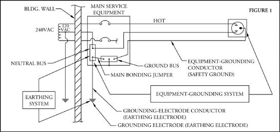
In the context of electrical systems, the word ground normally causes people to think of a connection to a water pipe or a ground rod. The National Electrical Code defines ground as a conducting connection, whether intentional or accidental between an electrical circuit or equipment and earth or some conducting body that serves in place of the earth. Grounded is defined as “Connected to earth or to some conducting body that serves in place of the earth”. Note that the phrase “or some conducting body that serves in place of the earth” appears in the definitions for ground and grounded. This means a ground can be established without a connection to earth as long as connection is made to “some conducting body that serves in place of the earth”. To clearly understand the purpose of grounding electrical systems and equipment, the subject of grounding must be divided into two categories: earth grounding and equipment grounding. People often confuse these two. Such confusion can result in misapplication of earth- and equipment-grounding practices and lead to a system that is expensive, inefficient, and even unsafe. The various components of equipment- and earth-grounding systems appear in Figure 1 below.
Earth-Grounding System
The basic purpose of an earth-grounding system is to protect the electrical system and equipment from super-imposed voltages caused by lightning and accidental contact with higher voltage systems. The earth-ground connection also prevents the buildup of static charges on equipment and materials.
An additional purpose of the earth ground is to establish a zero-voltage reference point for the system. This purpose is the one that is important to ensure proper performance of sensitive electronic and communication equipment.
In an earth electrode system, the resistance consists of three components: (a) resistance of the electrode and the connections to it, (b) the contact resistance of the electrode to the adjacent earth, and (c) the resistance of the earth surrounding the electrode. The majority of the resistance is from the earth surrounding the electrode. Thus, the resistivity of the soil around an electrode is the key factor determining the resistance of the system.
Soil resistivity varies widely, and moisture content and temperature affect it. There are three strategies that may overcome high soil resistivity: (a) drive the electrode deeper, (b) use multiple electrodes connected together, or (c) treat the soil. Doubling the depth of any electrode will reduce system resistance by approximately 40%. However, in many areas, due to bedrock or other soil conditions, it may not be possible to drive the electrode to the desired depth.
Where deep-driving an electrode is not practical, multiple electrodes connected in parallel may succeed. Multiple electrodes tend to conform to the law of parallel resistors, however. Thus, to reach a 50% reduction in resistance, the electrodes have to be spaced a distance approximately ten to twenty times their driven depth, which is impractical. Spacing electrodes at a distance twice their driven depth achieves about a 40% reduction in resistance each time the number of electrodes doubles.
Where deep driving or using multiple electrodes is impractical, consider chemically treating the soil to reduce the resistance. Dig a trench three to four feet in diameter around the electrode and fill it with a salt (magnesium sulfate, copper sulfate, or rock salt, for example). Note: Use this method only after exhausting all others. Because soil treatment can possibly contaminate the local water supply, obtain approval from the appropriate environmental authorities before proceeding.
One advantage of soil treatment to reduce resistance is that it minimizes seasonal variations. A disadvantage is that the salt will gradually dissipate and require replacement. A second disadvantage is that corrosion of the electrodes may occur under certain soil and moisture conditions.
Equipment-Grounding System
Equipment grounding serves several functions. First, it is the primary way to protect personnel from electrocution. Secondly, it is the most critical common link to all electronic components of a data, telecommunications, or process-control system. For this reason, ineffective equipment grounding causes equipment to operate at different electrical ground-reference voltages. These voltage differences among system components or nodes disrupt data-flow quality and can bring the network to a total halt. When industrial process-control equipment experiences a sudden, inexplicable system halt, a grounding problem probably exists. The Electric Power Research Institute (EPRI) states that “better than 80% of all electronic system failures that are attributed to power anomalies are actually the result of electrical wiring or grounding errors or are generated by other loads within the customer’s facility.”
Effective equipment grounding aims at several objectives:
- To minimize to the greatest extent possible the appearance of any voltages on equipment enclosures. This provides protection from serious shock or electrocution of personnel in contact with the enclosure.
- To provide an intentional path of ample current-carrying capacity and low impedance to insure rapid operation of circuit’s overcurrent protection under ground fault conditions.
- To establish and maintain a zero-voltage reference point, at the location of sensitive electronic equipment, that will contribute to proper underground fault conditions.
The National Electrical Code (NEC) Section 250-51, discusses effective grounding. The NEC says that an effective grounding path –the path to ground from circuits, equipment, and metal enclosures for conductors–shall;
- Be permanent and continuous.
- Have capacity to conduct safely any fault current likely to be imposed on it.
- Have sufficiently low impedance to limit the voltage to ground and to facilitate the operation of the protective devices in the circuit.
The NEC also says:
- The earth shall not be used as the sole equipment-grounding conductor.
To achieve the objectives, an equipment-grounding system must meet all four-code requirements. Failure to meet all four requirements means there is not effective grounding; the system is unsafe.
Fault Protection
Properly installed, the equipment-grounding system protects personnel from shock hazard and equipment from damage or destruction resulting from faults or electrical noise.
Install equipment-grounding conductors with sufficient capacity and low impedance throughout the AC distribution system so that overcurrent devices (fuses and circuit breakers) operate promptly when a ground fault occurs. Throughout the distribution system, the equipment-grounding conductors must run in the same conduit or raceway as the supply conductors. The NEC–Section 250-51, 250-91(b), and others–requires this to ensure low-impedance paths for fault currents.
When a ground fault occurs, the following segments of the grounding system must carry practically the entire fault current:
- The equipment grounding conductor (safety ground)
- The main bonding jumper
- The grounded conductor (neutral) from the service equipment to the transformer neutral point
The following segment of the grounding system should not carry the fault current:
- The grounding electrode conductor (earthling conductor)
- The grounding electrode (earthling electrode).
Effective grounding ensures instantaneous operation of the overcurrent device when a ground fault occurs. When there is accidental contact between an energized electrical conductor and the metallic frame or cabinet, the frame or cabinet becomes energized to the same potential as the energized conductor. To instantaneously eliminate this voltage, the equipment-grounding system must present a low impedance path from the energized frame or cabinet to the zero-potential, reference-ground junction at the service equipment or to the secondary of a separately derived system.
Effective Grounding
Figure 2 below illustrates a typical 120VAC circuit operating under normal conditions. The earth-electrode system establishes a zero-voltage reference at the main panel while the equipment-grounding system extends this zero-voltage reference from the main panel to the equipment’s metallic enclosure (cabinet).
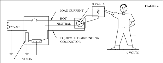
Under normal operating conditions, the load current flows on the hot and neutral conductors, and no current flows on the equipment-grounding conductor. The equipment-grounding conductor to the equipment enclosure extends the zero-voltage reference established by the grounding electrode at the main service equipment. Maintaining zero volts on the equipment enclosure protects the operator against electrical shock. The equipment ground also provides a zero-voltage reference for the logic circuits in the equipment.
Figure 3 below illustrates the same 120VAC circuit under a ground fault condition. When a ground fault occurs, the equipment-grounding conductor becomes the return path for fault current to flow back to the source. The equipment enclosure will have a shock voltage resulting in a current flow through the operator’s body until the circuit breaker trips and opens the circuit. Therefore, a low impedance path is essential so that sufficient fault current occurs to cause the instantaneous operation of the circuit breaker.
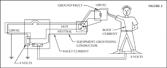
The operating time of the overcurrent device is a function of current flow through the device. The higher the current – the shorter the operating time. High impedance, in the equipment-grounding conductor, reduces the level of fault current and extends the operating time of the device. This condition exposes the operator to a prolonged and dangerous shock that could be lethal. A sufficiently low impedance of the equipment-grounding conductor increases fault current and reduces the operating time of the overcurrent device. This impedance value should never exceed an absolute maximum value of one (1) ohm. It is critical to note that this reading (in ohms) is impedance and not resistance. Measuring it, therefore, requires the use of an (AC) impedance tester that measures the impedance of a conductor from the point of test back to the main electrical service, while accurately diagnosing other wiring problems in the circuit. Do not use an ohmmeter or digital multi-meter (DMM).
Outlet testers, digital voltmeters, and DMMs have been widely misapplied in the testing of AC power systems to quantify impedance. While DMMs are capable of quantifying DC resistance values, they cannot measure impedance in AC electrical systems. Impedance is the vector sum of resistance, inductive reactance, and capacitive reactance. When testing for impedance, do not assume any specific relationship between reactance and resistance. Resistance and impedance are not equal in an AC circuit.
The level of personnel safety, equipment protection, and equipment performance is a direct function of the impedance of the equipment-grounding-conductor. In providing overcurrent protection under ground fault conditions, the earth-electrode system plays no role whatsoever in the performance of the equipment-grounding system. Attempting to use the earth-electrode system to accomplish the safety objectives of the equipment-grounding system can prove fatal.
The most important, but often overlooked step in electronic equipment installations is the routine verification of the electrical wiring and grounding system supplying the electronic equipment. Without such verification, undetected problems may manifest themselves as intermittent malfunctions and failures.
Guidelines to Follow
Tables 1 and 2 show maximum allowable impedances for grounding or neutral conductors. Values shown are within the requirements of the NEC, Canadian Electric Code, and IEEE standards. Using the proper testing instruments, always verify that the quality of the grounding or neutral conductors conforms to allowable impedance values. Where measurements show excessive impedance, take immediate steps to find and replace fault and tighten all connections. Some circumstances may require rerouting of conductors.
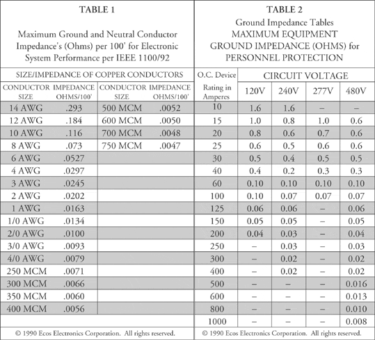
The objective of using specialized instruments is accurately and quickly to locate wiring errors, poor quality (high impedance) conductors, and other problems causing safety and equipment-performance problems. The maximum allowable impedance value for personnel safety for a 15 Amp circuit is one (1) ohm and for equipment performance, one-quarter (.25) ohm. As circuit breaker ratings increase, impedance values become lower.
By following the guidelines of the IEEE Emerald Book, Recommended Practice for Powering and Grounding Sensitive Electronic Equipment, you can enhance personnel safety and equipment performance. Take the following steps:
- Conduct a wiring verification test. Measure all voltages, current, phase rotation, load balance, equipment grounding conductor impedance, neutral impedance, and the presence of the required neutral-ground bond at the service equipment.
- Test for wiring errors at the panel or outlet of interest. Check for missing connections, including open equipment-grounding conductors, open neutrals, and open-phase conductors.
- Test for improper connections including reversed phase/neutral or reversed neutral/equipment- grounding.
- Test for poor quality connections, which voltage and impedance measurements also will detect.
During visual inspection, ask the following:
- Is the panel dedicated to serving only electronic equipment?
- Is proper wire size used for the feeder and branch circuit conductors?
- Is the feeder neutral sized at 200% of the wire size of the hot conductors?
- Is an insulated equipment-grounding conductor installed with the feeder conductors?
- Are individual branch circuits installed to supply only electronic loads?
Document all test results on a site certification report. This will establish a benchmark for any future testing. Purchase power-conditioning and power-protection products only after determining that the facility wiring and grounding are trouble free and of high quality.
Writing clear, concise specifications to cover the grounding requirements of sensitive electronic equipment and supplementing those specifications with diagrams will minimize incorrect installations in your facility. Remember, perform verification and routine testing of electrical wiring and grounding with ground impedance testers. It is the final, critical step to ensure the performance of local area networks and electronic systems and the safety of personnel.
Equipment and Earth-Grounding System Components:
- Grounded Conductor (neutral): A system or circuit conductor that is intentionally grounded.
- Equipment-Grounding Conductor: The conductor used to connect the noncurrent carrying metal parts of equipment, raceways, and other enclosures to the system grounded conductor and/or the grounding electrode conductor at the service equipment or at the source of a separately derived system.
- Main Bonding Jumper: The connection between the grounded conductor (neutral) and the equipment- grounding conductor (safety ground) at the service entrance equipment.
- Grounding-Electrode Conductor (earthling conductor): The conductor used to connect the grounding electrode to the equipment-grounding conductor (safety ground) and/or to the grounded conductor (neutral) at the service equipment or at the source of separately derived system.
- Grounding Electrode: A current carrying (metallic) item such as a rod, plate, pipe, etc. imbedded in the earth.