This article offers a basic overview of SCADA telemetry network system information. It is intended to help educate and equip you for future SCADA and/or telemetry system decisions.
Supervisory Control and Data Acquisition (SCADA) is a system that allows an operator at a master facility to monitor and control processes that are distributed among various remote sites.
A properly designed SCADA system saves time and money by eliminating the need for service personnel to visit each site for inspection, data collection/logging or make adjustments. Real-time monitoring, system modifications, troubleshooting, increased equipment life, automatic report generating . . . these are just a few of the benefits that come with today’s SCADA system.
Other benefits SCADA Systems provide:
- Reduces operational costs
- Provides immediate knowledge of system performance
- Improves system efficiency and performance
- Increases equipment life
- Reduces costly repairs
- Reduces number of man-hours (labor costs) required for troubleshooting or service
- Frees up personnel for other important tasks
- Facilitates compliance with regulatory agencies through automated report generating
- And more . . .
As technology continues to advance, SCADA systems will become recognized as a standard for any processing site. But from the hundreds of system providers available today, which one will you listen to? What system will be right for your application? Who will you choose to partner with and why?
Choosing a SCADA system provider that will design a system applicable to your needs can be an overwhelming and confusing task. With little or no knowledge of SCADA and Data Acquisition systems and an incomplete pre-system assessment, the decisions made can be costly mistakes. Too often the decisions are based on . . .
Price:
The quality of the work and components suffer when vendors are eager to get to the bottom to win the low bid. Vendors will then indiscriminately find ways to still make a profit. You get what you pay for!
Proprietary Equipment:
Do not eliminate your options. After proprietary equipment has been installed as “standard” for the system, the customer can be held hostage and be forced to pay an inflated price. In addition, a closed protocol leaves the end-user with fewer options for integrating future equipment from vendors as well as being vulnerable to lack of support and inability to replace failed components due to obsolescence and/or company shutdown.
Excessively Complex or Customized Equipment:
Many operators are “wowed” by system specialists demonstrating all the capabilities of their SCADA system. After installation, the system is too complex for them to understand, operate and support. What you will have is a very expensive system running at minimum while the operator continues to work the old habits. The only recourse is to purchase expensive training and/or service contracts, which do not always guarantee prompt and professional service. Some SCADA systems have been shut down for months while waiting for a single source of technical support to arrive. Keep it simple wherever possible.
Years of Experience:
Be careful. There are a host of reputable SCADA providers with years of experience and knowledgeable expertise that have designed systems that are too broad, expensive and/or do not work. Many companies use this line as if it sets them apart from all the rest. Experience and knowledge is important but only as a starting point when determining what vendor is right for you.
Sales People and/or Flashy Marketing:
Good sales and marketing strategies are meant to produce “top-of-mind”, “foot-in-the-door” results. They may lure you or pressure you rather than equip you in making a sound decision based on all factors that affect optimum system performance.
These and other costly mistakes can be avoided through knowing, understanding, and carefully assessing your particular needs. For some, that may mean skimming through this article and then focusing on Table A and B below. For others, with little or no SCADA knowledge, you should read and become familiar with the background information provided below.We at EPG Companies Inc. have prepared this Pre SCADA System Assessment to help equip you in determining what SCADA or Data Acquisition system is right for you. If you have any questions or comments after reviewing this assessment, please call us at 800-443-7426 and ask for a SCADA or Data Acquisition specialist. We have served the industry for over 20 years manufacturing systems that save time and money, are easy to use, and give years of dependable process control.
A BRIEF HISTORY
The development of SCADA can be traced back to the early 1900’s with the advent of telemetry. Telemetry involves the transmission and collection of data obtained by sensing real-time conditions. The monitoring of remote conditions became possible with the convergence of electricity, telegraph, telephone, and wireless communication technology. Throughout the last century, more industries, such as gas, electric, and water utilities, used telemetry systems to monitor processes at remote sites.
SCADA began in the early sixties as an electronic system operating as Input/Output (I/O) signal transmissions between a master station and a Remote Terminal Unit (RTU) station. The master station would receive the I/O transmissions from the RTU through a telemetry network and then store the data on mainframe computers.
In the early seventies, DCS (Distributed Control Systems) were developed. The ISAS5.1 standard defines a distributed control system as a system that while being functionally integrated consists of subsystems, which may be physically separate and remotely located from one another. Large manufacturers and process facilities utilized DCS primarily because they required large amounts of analog control.
Further development enabled Distributed Control Systems to use Programmable Logic Controllers (PLC), which being more intelligent than RTUs, have the ability to control sites without taking direction from a master.
In the late nineties, the differences between SCADA and DCS blurred. SCADA systems had DCS capabilities. DCS had SCADA capabilities. Systems were customized based on certain control features built in by designers. Now with the Internet being utilized more as a communication tool, control functions that were once old telemetry systems are becoming more advanced, interconnected and accessible. Automated software products are being developed to exploit the inter-connectivity of the Internet and certain portals can connect to a SCADA system and download information or control a process.
Good SCADA systems today not only control processes but are also used for measuring, forecasting, billing, analyzing and planning. Today’s SCADA system must meet a whole new level of control automation, interfacing with yesterday’s obsolete equipment yet flexible enough to adapt to tomorrow’s changes.
Whether you need a new system or are upgrading an older one, it is important to know the system components before you decide on who to talk with and what equipment you will need for your particular application.
SYSTEM COMPONENTS
SCADA systems typically have four major elements: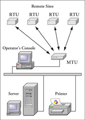
- Master Terminal Unit (MTU)
- Remote Terminal Unit (RTU)
- Communication Equipment
- SCADA Software
1. Master Terminal Unit (MTU)
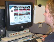
The Master Terminal Unit is usually defined as the master or heart of a SCADA system and is located at the operator’s central control facility. The MTU initiates virtually all communication with remote sites and interfaces with an operator. Data from remote field devices (pumps, valves, alarms, etc.) is sent to the MTU to be processed, stored and/or sent to other systems. For example, the MTU may send the data to the operator’s display console, store the information, and then send an operator’s initiate command to a field pump’s RTU.
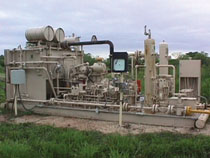
2. Remote Terminal Unit (RTU)
The Remote Terminal Unit is usually defined as a communication satellite within the SCADA system and is located at the remote site. The RTU gathers data from field devices (pumps, valves, alarms, etc.) in memory until the MTU initiates a send command. Some RTUs are designed with microcomputers and programmable logic controllers (PLCs) that can perform functions at the remote site without any direction from the MTU. In addition, PLCs can be modular and expandable for the purpose of monitoring and controlling additional field devices. Within the RTU is the central processing unit (CPU) that receives a data stream from the protocol that the communication equipment uses. The protocol can be open like Modbus, Transmission Control Protocol and Internet Protocol (TCP/IP) or a proprietary closed protocol. When the RTU sees its node address embedded in the protocol, data is interpreted and the CPU directs the specified action to take.
During the sixties, many manufacturers developed RTUs with communicative functions that performed a few specific tasks such as monitor and control digital and analog field devices. These “all-in-one” RTUs needed constant communication with the MTU in order to operate. A wide variety of programming languages were used that were not well known or supported. In the eighties the first “micro” PLCs were introduced as the first “Open Architecture” technology which has evolved and gained acceptance as today’s preferred alternative to closed, proprietary systems.
Some manufacturers, like EPG’s SCADA division NBT, now make Remote Access PLCs (RAPLC) specifically designed for SCADA and Data Acquisition applications. With NBT’s PLC system, you can:
- Perform control
- Check site conditions
- Re-program anytime from anywhere
- Have any alarm or event trigger a call to your personal computer
This can all be done from a single, master site and the system can control one or multiple sites. Both industry representatives and customers welcome these “smart” PLCs because they provide remote programmable functionality while retaining the communications capability of an RTU.
3. Communication Equipment
The way the SCADA system network (topology) is set up can vary with each system but there must be uninterrupted, bidirectional communication between the MTU and the RTU for a SCADA or Data Acquisition system to function properly. This can be accomplished in various ways, i.e. private wire lines, buried cable, telephone, radios, modems, microwave dishes, satellites, or other atmospheric means, and many times, systems employ more than one means of communicating to the remote site. This may include dial-up or dedicated voice grade telephone lines, DSL (Digital Subscriber Line), Integrated Service Digital Network (ISDN), cable, fiber optics, WiFi, or other broadband services.
There are many options to consider when selecting the appropriate communication equipment and can include either a public and/or private medium. Public medium is a communication service that the customer pays for on a monthly or per time or volume use. Private mediums are owned, licensed, operated and serviced by the user. If you choose to use a private medium, consider the staffing requirements necessary to support the technical and maintenance aspects of the system.
Private Media Types:
Private Wire
Sometimes it makes sense to string or bury your own cable between sites to provide continuous communication. This type of media usually is limited to low bandwidth modems.
Wireless
(Spread Spectrum Radio)
This media type is license-free and available to the public in the 900 MHz and 5.8GHz bands. The higher the frequency used in the system, the more “line of sight” it becomes. Some Spread Spectrum radio units have the ability to span distances by re-strengthening signals for the next radio in line, acting like a repeater for other units in the network. Spread Spectrum radio modems generally have built in error correction, encryption and other features that make them a reliable, secure and long-lasting solution for network communication.
(Microwave Radio)
Microwave radio transmits at high frequencies through parabolic dishes mounted on towers or on top of buildings. This media uses point-to-point, line-of-sight technology and communications may become interrupted at times due to misalignment and/or atmospheric conditions.
(VHF/UHF Radio)
Good for up to 30 miles, VHF/UHF radio is an electromagnetic transmission with frequencies of 175MHz-450MGz-900MHz received by special antennas. A license from the FCC must be obtained and coverage is limited to special geographical boundaries.
Public Media Types:
(Telephone Company)
There are different services that your local telephone company can provide including: Switched Lines, Private Leased Lines, Digital Data Service, Cellular and PCS/CDPD.
- Switched Lines: Public Switch Telephone Network (PSTN) and Generally Switched Telephone network (GSTN) are dial-up voice and data transmission networks furnished by your local telephone company.
- Private Leased Lines: Private Leased Lines (PLL) are permanently connected 24 hours a day between two or more locations and used for analog (continuously varying signal) data transmission.
- Digital Data Service: Digital Data Service (DDS) is a private leased line with a special bandwidth used to transfer data at a higher speed and lower error rate. This service is applicable for computer-to-computer links.
- Cellular: This service is equivalent to Switched Line services over landlines.
- PCS/CDPD: This service is provided by cellular companies on a monthly fee or traffic volume basis and is used when continuous communication is needed.
Other Media Types:
(WiFi-SMR)
Sometimes it makes sense to use the infrastructure of another company. WiFi equipment utilizes broadband with high data rates and is used in a “time-share” basis to communicate between sites of the system. This media type generally requires advanced protocols like TCP/IP and network type connections.
(Satellite-Geosychronous/LEO)
Geosynchronous satellite’s orbits are synchronous with the earth’s orbit and remain in the same position with respect to the earth. These satellites use high frequency transmissions received by parabolic dish antennas. Low Earth Orbit (LEO) satellites hand off signals to other satellites for continuous coverage and latency times are less than geosynchronous satellites due to the lower orbit.
4. SCADA Software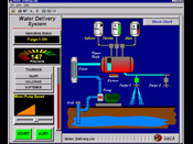
A typical SCADA system provides a Human Machine Interface (HMI) allowing the operator to visualize all the functions as the system is operating. The operator can also use the HMI to change set points, view critical condition alerts and warnings, and analyze, archive or present data trends. Since the advent of Windows NT, the HMI software can be installed on PC hardware as a reliable representation of the real system at work.
Common HMI software packages include Cimplicity (GE-Fanuc), RSView (Rockwell Automation), IFIX (Intellution) and InTouch (Wonderware). Most of these software packages use standard data manipulation/presentation tools for reporting and archiving data and integrate well with Microsoft Excel, Access and Word.
Web-based technology is widely being accepted as well. Data collected by the SCADA system is sent to web servers that dynamically generate HTML pages. These pages are then sent to a LAN system at the operator’s site or published to the Internet.
THE MICROPROCESSOR OPTION
Now that you have a basic understanding of the SCADA system components, you may want to consider utilizing a microprocessor (MP) and/or a PLC-based SCADA system over a basic RTU or a proprietary system for the following reasons:
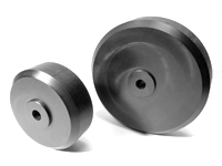
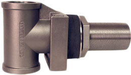
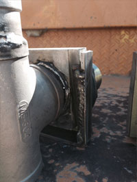
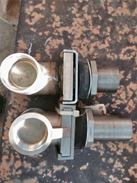
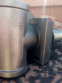
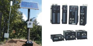
M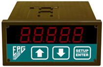 Ps, like MTUs, can continuously collect, process and store data, operating independently from the MTU through “intelligent” programming. In addition, by utilizing an EPG microprocessor-based level meter (pictured), you can have a robust SCADA system with both a master and a local display that automatically gathers, processes, and reports data necessary to comply with local, state and federal regulations in formats that integrate well will Microsoft Excel, Access and Word.
MPs can provide security and monitoring of door switches, heat and motion detectors. Managers/operators can be informed 24 hours a day through automatic email, paging and dial-up call features. Multiple users can easily be added and if open architecture protocol is used, future equipment can easily be integrated. Since MPs have no moving parts, they are extremely reliable and can be designed to be repairable with components that any local electrical distributor supplies.
MP-based SCADA system can reduce the number of man-hours needed for on-site visual inspections, adjustments, data collection and logging. Continually monitoring and troubleshooting potential problems increases equipment life, reduces service calls, reduces customer complaints and increases system efficiency. Simply put, open-architecture, MP-based SCADA systems are an excellent means for process control facilities to save time and money.
FEATURES & BENEFITS
Now lets look at some of the features and benefits you’ll receive from a properly engineered PLC-based SCADA system.
You may be able to think of some additional benefits that would be applicable to your own site. Begin by answering the following questions:
SCADA systems of today are an excellent means for operators of process control sites to save time and money. But from the hundreds of SCADA system providers to choose from, one poor decision may lead you down the path to countless frustrations, inefficiencies and unnecessary expenses. We at EPG Companies Inc. have prepared this pre-system assessment to help prepare the way for you to purchase a SCADA system that will give you years of cost-effective and dependable process control while leaving you open for tomorrows expansions and options. In closing consider the following:
The ROI (return on investment) and benefits produced by a properly engineered PLC SCADA system will far outweigh your initial investment if the right equipment is chosen and installed correctly. To help facilitate a suitable and beneficial choice, consider answering the following:
EPG equipment uses the open architecture Modbus protocol, is well documented, and will integrate into any existing system. For over 20 years we have been manufacturing dependable, cost-effective process control solutions for thousands of industry professionals. If you have any questions or would like to talk to a Data Acquisition, SCADA or Telemetry hardware specialist, please give us a call at 800-443-7426. We look forward to partnering with you.